
VRF HVAC System Diagram
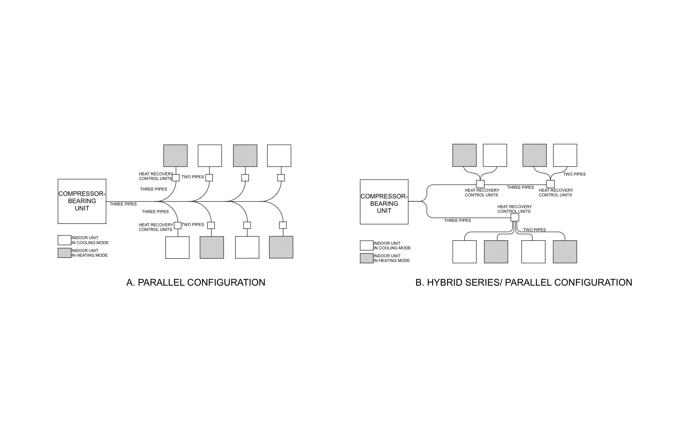
Variable refrigerant flow (VRF) lets one office run the heat while the conference room next door runs the AC, all from a single outdoor unit. ArcSite's VRF HVAC system diagram puts a parallel and a hybrid piping layout side by side.
Opens right in your browser — no install. Make it yours within minutes.


Free access to over 1,200 shapes and blocks included with the ArcSite CAD app
Key Features
This VRF HVAC system diagram includes:
- Parallel configuration with eight indoor units
- Hybrid series/parallel configuration with eight indoor units
- Compressor-bearing unit feeding each layout
- Three-pipe runs to the heat recovery control units
- Two-pipe runs from each control unit to its indoor units
- Legend for indoor units in cooling and heating mode
In the parallel layout every indoor unit gets its own heat recovery control unit, while the hybrid layout shares one control unit across two to four indoor units, so it needs fewer control units for the same zones.
What is a VRF HVAC System?
A VRF system runs refrigerant from one compressor-bearing unit to many indoor units, and heat recovery control units let some zones heat while others cool. Sketch the piping over your customer's floor plan in ArcSite to count the indoor units and control units the job needs.

Trusted by the Pros. Honored for Innovation.





HVAC & Mechanical
templates you might like

FAQ
It's a three-pipe heat recovery system. Three pipes run to each heat recovery control unit, and two pipes run from there to each indoor unit.
Yes! You can copy indoor units and control units in ArcSite to match the zone count on your job.
Draw the system once on site and it goes straight into the proposal. No rebuilding the estimate back at the office.