
Tankless Water Heater Installation
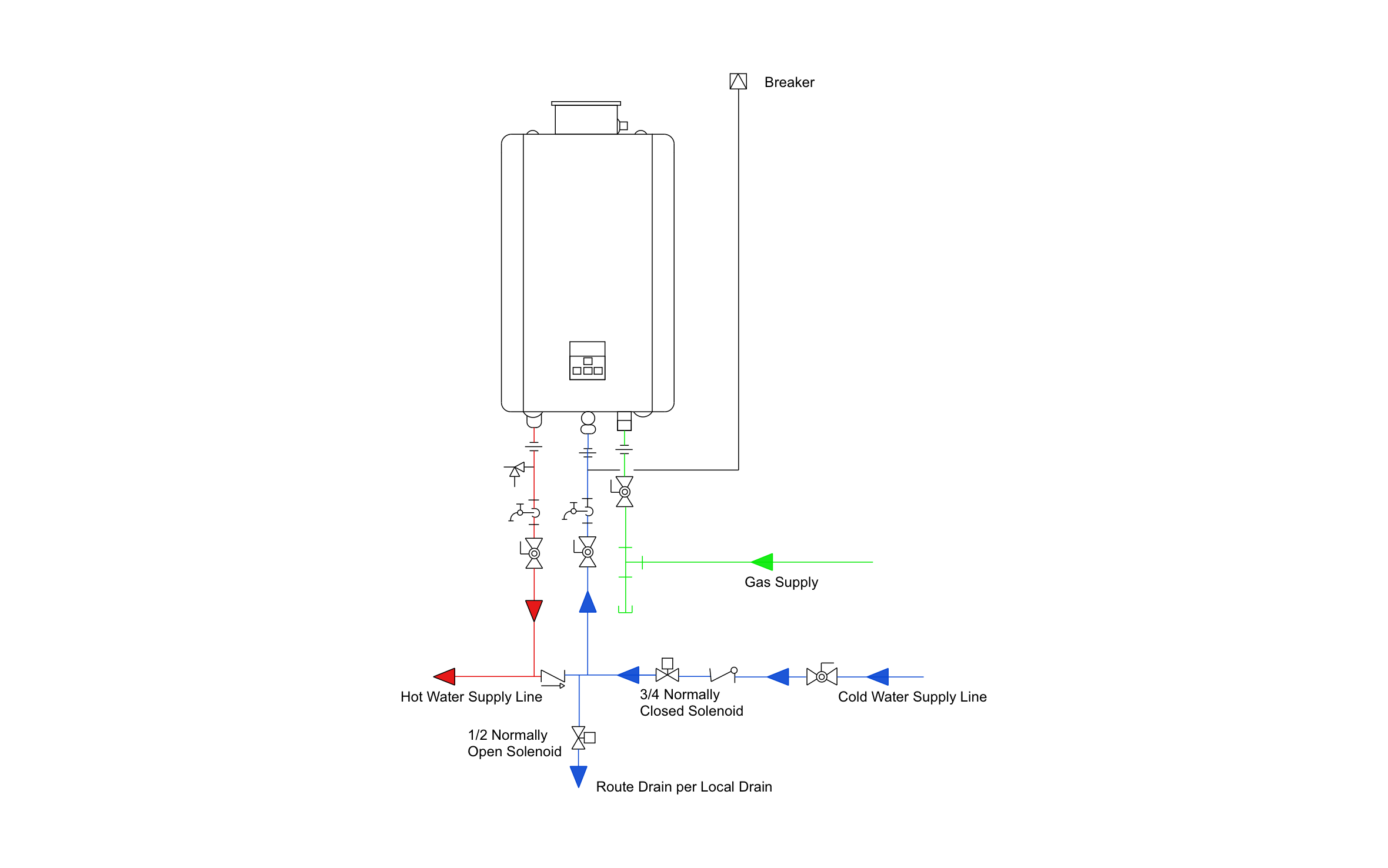
A tankless water heater makes hot water only when a tap opens, so there's no tank sitting full and losing heat between uses. ArcSite's tankless water heater installation diagram lays out every valve, line, and connection below the unit.
Opens right in your browser — no install.
Make it yours within minutes.


Free access to over 1,200 shapes and blocks included with the ArcSite CAD app
Key Features
This tankless water heater installation diagram includes:
- Gas tankless unit with a top vent connection
- Gas shutoff valve and sediment trap
- Breaker feeding the unit
- Pressure relief valve on the hot outlet
- Isolation valves with service ports
- Cold supply shutoff and check valve
- 3/4" normally closed solenoid on the cold line
- 1/2" normally open solenoid on the drain line
The gas line drops past the shutoff into a sediment trap before it reaches the unit, catching dirt and debris before it reaches the unit.
Key Considerations When Installing a Tankless Water Heater
Isolation valves with service ports on the hot and cold lines let you flush and descale the unit without disconnecting it from the plumbing. ArcSite lets you lay out those valves, the gas line, and the electrical feed on one drawing, so your installer and the inspector see the same plan.

Trusted by the Pros. Honored for Innovation.





Plumbing & Restroom Fixtures
templates you might like


FAQ
Only the vent connection on top of the unit. Add the full vent run, termination, and clearances in ArcSite to match the manufacturer's install manual.
Yes! Remove the gas line in ArcSite and size the breaker for the electric unit you're installing.
You can. Snap the vent, gas line, and valves on site and pin each photo to the spot it shows, giving the office a clear look at the install.