Boiler System Diagram
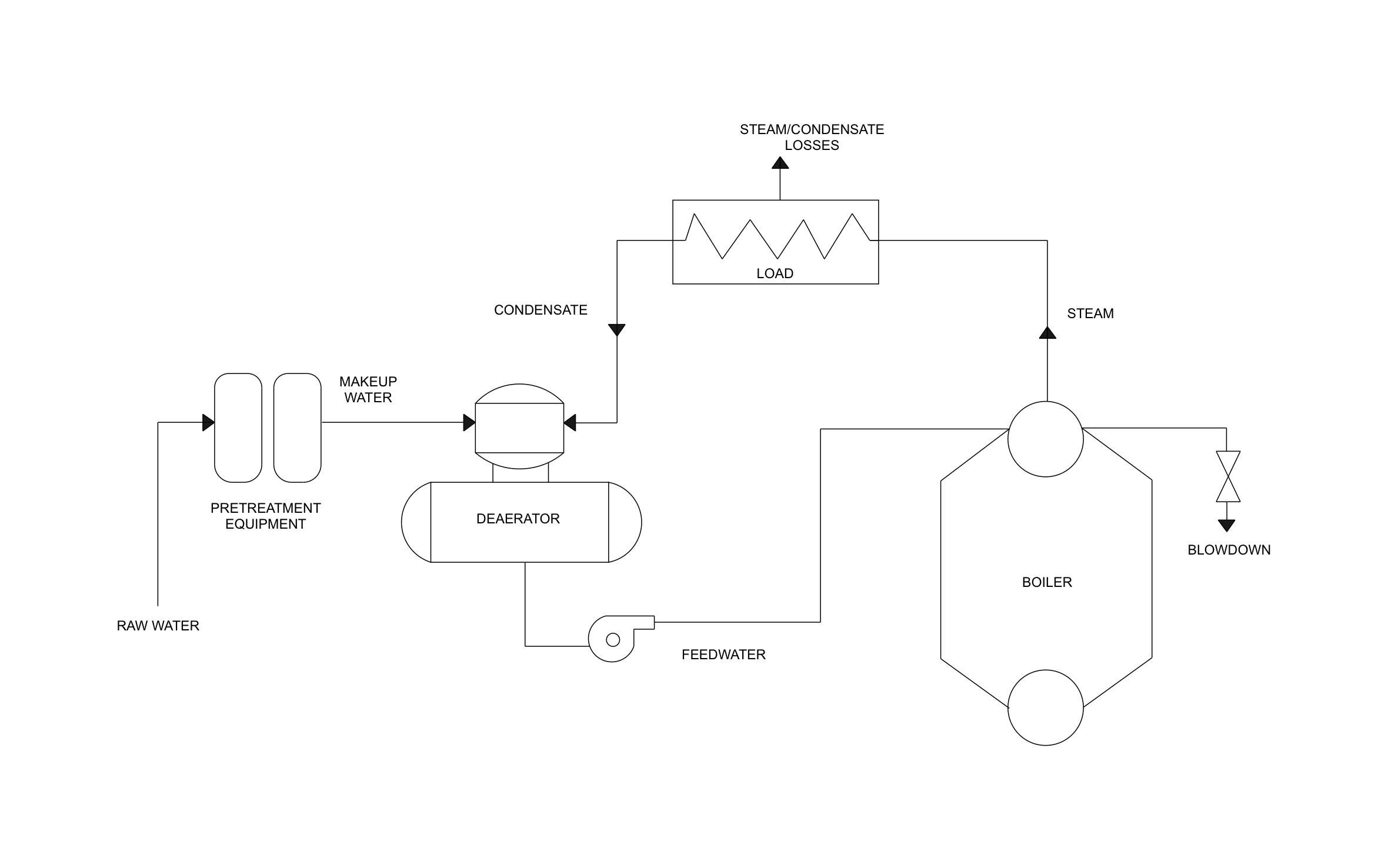
Clean feedwater flowing back to a steam boiler is what keeps a building warm or a production line running through winter. Trace that loop from raw water to deaerator to boiler and back with ArcSite's boiler system diagram.
Key Features
This boiler system diagram includes:
- Raw water feeding the pretreatment equipment
- Makeup water line into the deaerator
- Feedwater pump between the deaerator and the boiler
- Boiler with upper and lower drums
- Steam line out to the load and condensate line back
- Blowdown valve off the upper drum
- Steam and condensate losses marked at the load
Condensate and makeup water both land in the deaerator, so the drawing shows the one spot where fresh water replaces what the load loses.


Fully customizable


Industry specific


Professional & accurate designs
Trusted by Pros. Recognized by the Industry.
With top ratings across Software Advice, GetApp, and Capterra, professional contractors choose us for ease of use, powerful tools, and unmatched customer support.






Frequently asked questions
Is this diagram for a hot water boiler?
Can I add more loads to the steam line?
Can I use ArcSite for commercial mechanical jobs?