
Electric Fence Grounding Diagram
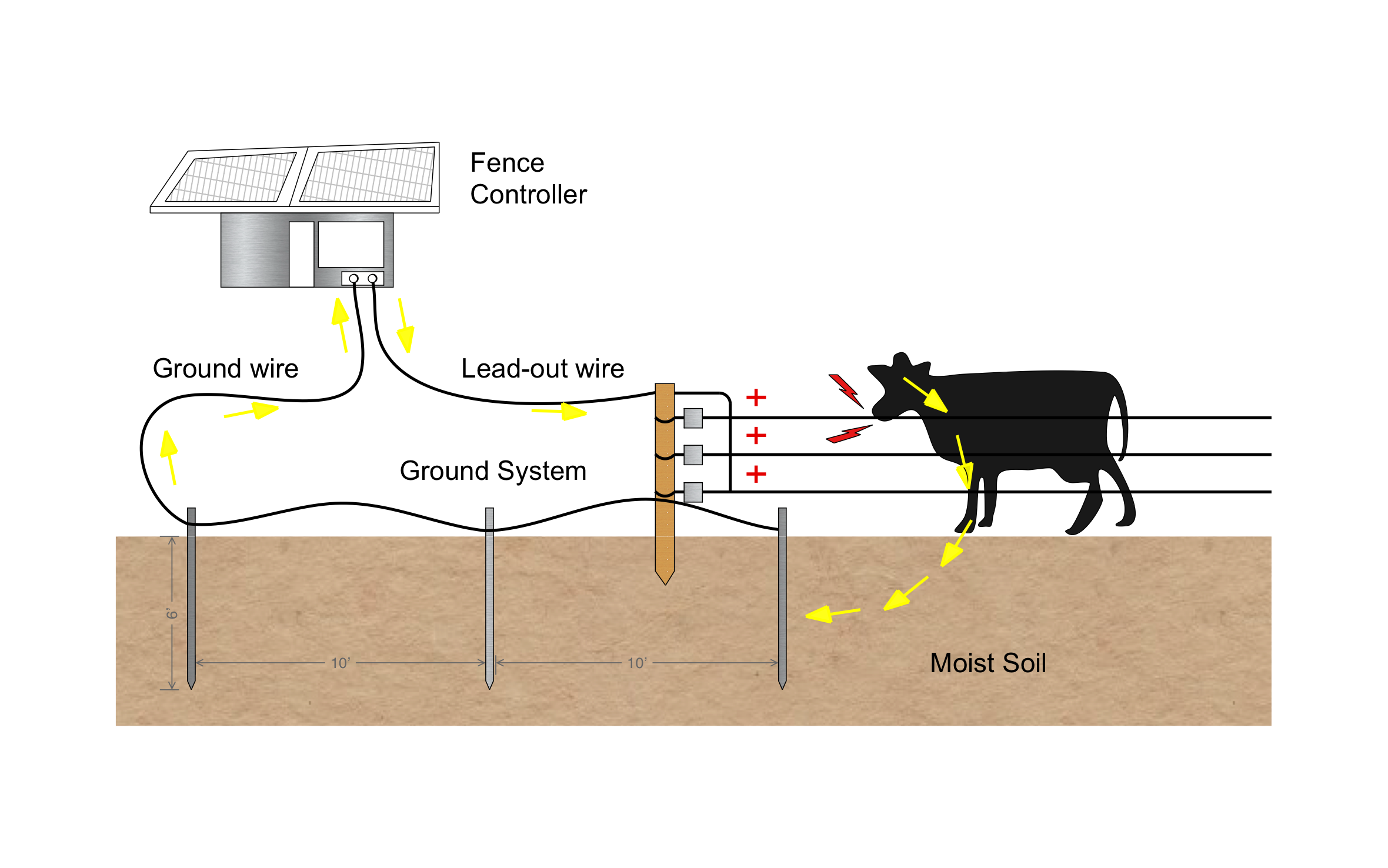
A well-grounded electric fence keeps livestock where they belong by putting the full shock on every hot wire. ArcSite's electric fence grounding diagram traces the full circuit from the fence controller, through the animal, and back through the ground rods.
Opens right in your browser — no install.
Make it yours within minutes.


Free access to over 1,200 shapes and blocks included with the ArcSite CAD app
Key Features
This electric fence grounding diagram includes:
- Solar-powered fence controller
- Lead-out wire to the first fence post
- Three hot wires on insulators
- Ground wire linking three ground rods
- Ground rods 6' deep
- 10' spacing between ground rods
- Arrows tracing current through the animal and the moist soil
The diagram puts the rods in moist soil for a reason: dry, sandy, or rocky ground carries the pulse back poorly, so rods need to reach moisture to close the circuit.
Why Electric Fence Grounding Matters
An animal only feels the shock when current makes it back through the soil to the ground rods, so a weak ground system means a weak fence. ArcSite lets you mark rod spacing and depth on your pasture drawing so your crew drives them right the first time.

Trusted by the Pros. Honored for Innovation.





Landscaping & Outdoor Living
templates you might like
FAQ
Three, each 6' deep and spaced 10' apart. Higher-output controllers call for more ground rod, and dry soil calls for rods long enough to reach moisture.
Absolutely. Add more hot wires, a ground-return wire, or extra rods to the drawing in ArcSite.
You can. Start the drawing from a satellite image of the property, trace the pasture runs, and mark every gate and corner brace.