Grease Trap Installation Diagram
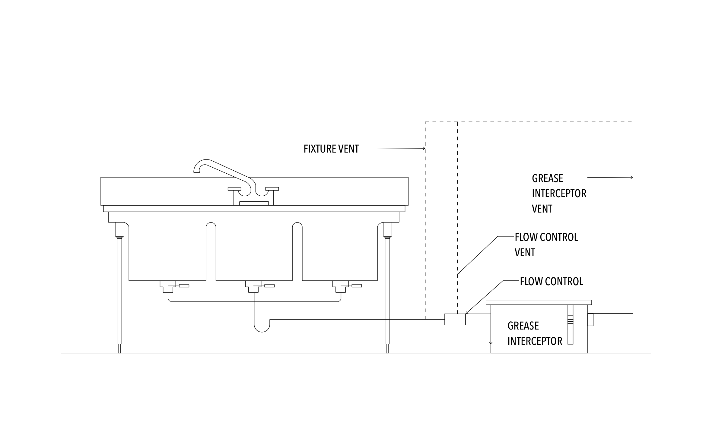
A working grease trap keeps a restaurant's drains flowing and its health inspections clean, even on the busiest prep days. ArcSite's grease trap installation diagram lays out the full run from the sink to the interceptor.




Free access to over 1,200 shapes and blocks included with the ArcSite CAD app
Key Features
This grease trap installation diagram includes:
- 3-compartment sink with a shared drain line
- Trap below the sink
- Flow control ahead of the interceptor
- Grease interceptor set at floor level
- Separate fixture vent, flow control vent, and grease interceptor vent
- Outlet line leaving the interceptor
Each of the three vents serves a different point in the line, so count all three when you price the job, not just the fixture vent.
Trusted by the Pros. Honored for Innovation.





Key Considerations When Installing a Grease Trap
A grease trap only works if water enters it slowly enough for grease to separate, which is why the flow control and its vent matter as much as the interceptor itself. ArcSite lets you place each component on this diagram and match the vent routing to the kitchen you're working in.

Commercial Kitchen & Hospitality
templates you might like
FAQ
The fixture vent serves the sink drain, the flow control vent lets the flow control draw in air, and the grease interceptor vent serves the interceptor itself. Each one keeps its part of the line from siphoning and losing its water seal.
Yes! You can change the sink in ArcSite and keep the rest of the drain and vent layout.
Absolutely. You can draw the whole kitchen, from prep sinks to floor drains, and export a PDF for the general contractor or health inspector.