Air Handler Installation Diagram
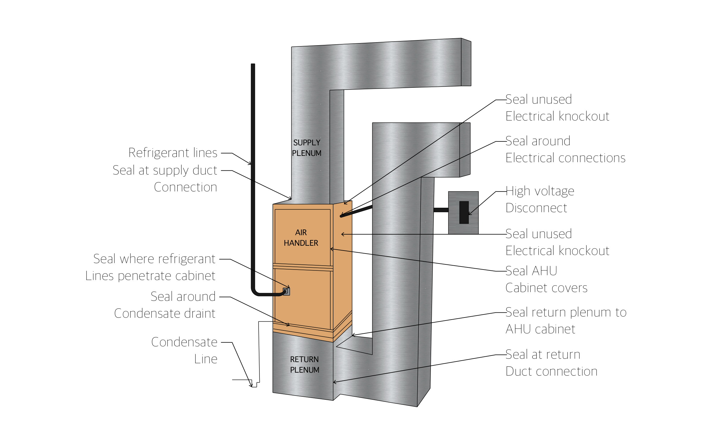
Sealed tight, an air handler pushes cooled air into the bedrooms instead of losing it to a dusty closet or attic. Start from ArcSite's air handler installation diagram to mark every seal point from the supply plenum down to the condensate line.
Key Features
This air handler installation diagram includes:
- Air handler cabinet between the supply and return plenums
- Refrigerant lines entering the side of the cabinet
- High voltage disconnect mounted beside the unit
- Condensate line running from the base of the cabinet
- Seal callouts at both duct connections
- Seal callouts for the cabinet covers and unused electrical knockouts
The drawing calls out two unused electrical knockouts, a pair of open holes that pull in dusty closet air if nobody seals them.


Fully customizable


Industry specific


Professional & accurate designs
Trusted by Pros. Recognized by the Industry.
With top ratings across Software Advice, GetApp, and Capterra, professional contractors choose us for ease of use, powerful tools, and unmatched customer support.





HVAC & Mechanical
templates you might like


Frequently asked questions
Does this diagram show refrigerant line sizes?
Can I flip this to a horizontal air handler?
Can I turn this drawing into a proposal?