Electrical Wiring Diagram
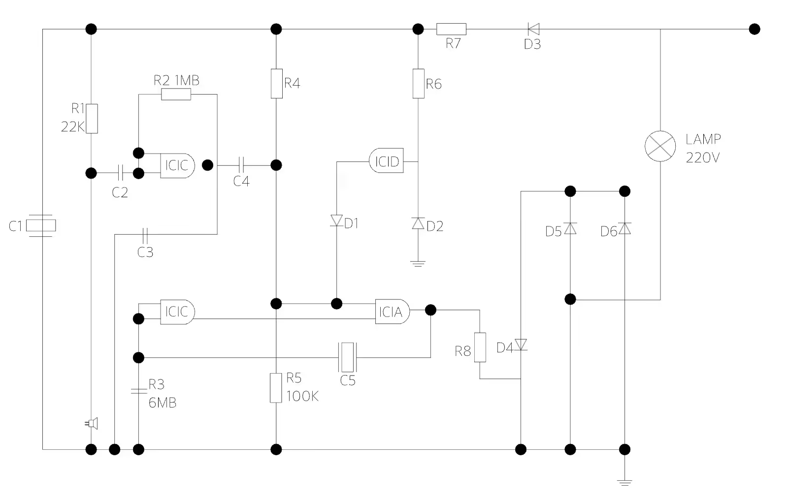
An electrical wiring diagram shows exactly how switches, resistors, and other components connect before anyone touches a wire, which matters most when a customer needs to sign off on the plan first. ArcSite's electrical wiring diagram lays those connections out, ready to adjust to a specific job.




Free access to over 1,200 shapes and blocks included with the ArcSite CAD app
Key Features
This electrical wiring diagram includes
- Resistor callouts (R1, R2, R3)
- Capacitor callouts (C1, C2, C3)
- Diode callouts (D1, D2, D3)
- Integrated circuit labels (IC1A, IC1B, IC1C)
- 220V lamp connection
- Power supply connection points
Each component is labeled with its own reference designator rather than a generic icon, worth pointing out if a customer or inspector needs to cross-reference the drawing against a parts list.
Trusted by the Pros. Honored for Innovation.





What is an Electrical Wiring Diagram?
An electrical wiring diagram is a schematic that shows how components like switches, resistors, and capacitors connect within a system. In ArcSite, you can mark up this wiring diagram with your own component labels and connections for the job you're documenting.

Electrical & Power
templates you might like

FAQ
An accurate electrical wiring diagram ensures that circuits, outlets, fixtures, and wiring runs are laid out precisely. This reduces the likelihood of errors, helps prevent safety hazards, and facilitates compliance with electrical codes and standards.
ArcSite gives you precise drawing tools, layer management, and easy-to-edit templates, so it's easier to update designs, verify measurements, and share documentation with electricians and inspectors.
ArcSite provides a free 14-day trial, allowing you to explore its features and assess how it fits into your workflow. After the trial, you can select a subscription plan that aligns with your project or business requirements.